UBC - FSAE Chassis Design & Manufacturing
- Michael Rooney

- Dec 21, 2020
- 2 min read
Updated: Jan 2, 2021
University of British Columbia - Formula Society of Automotive Engineers

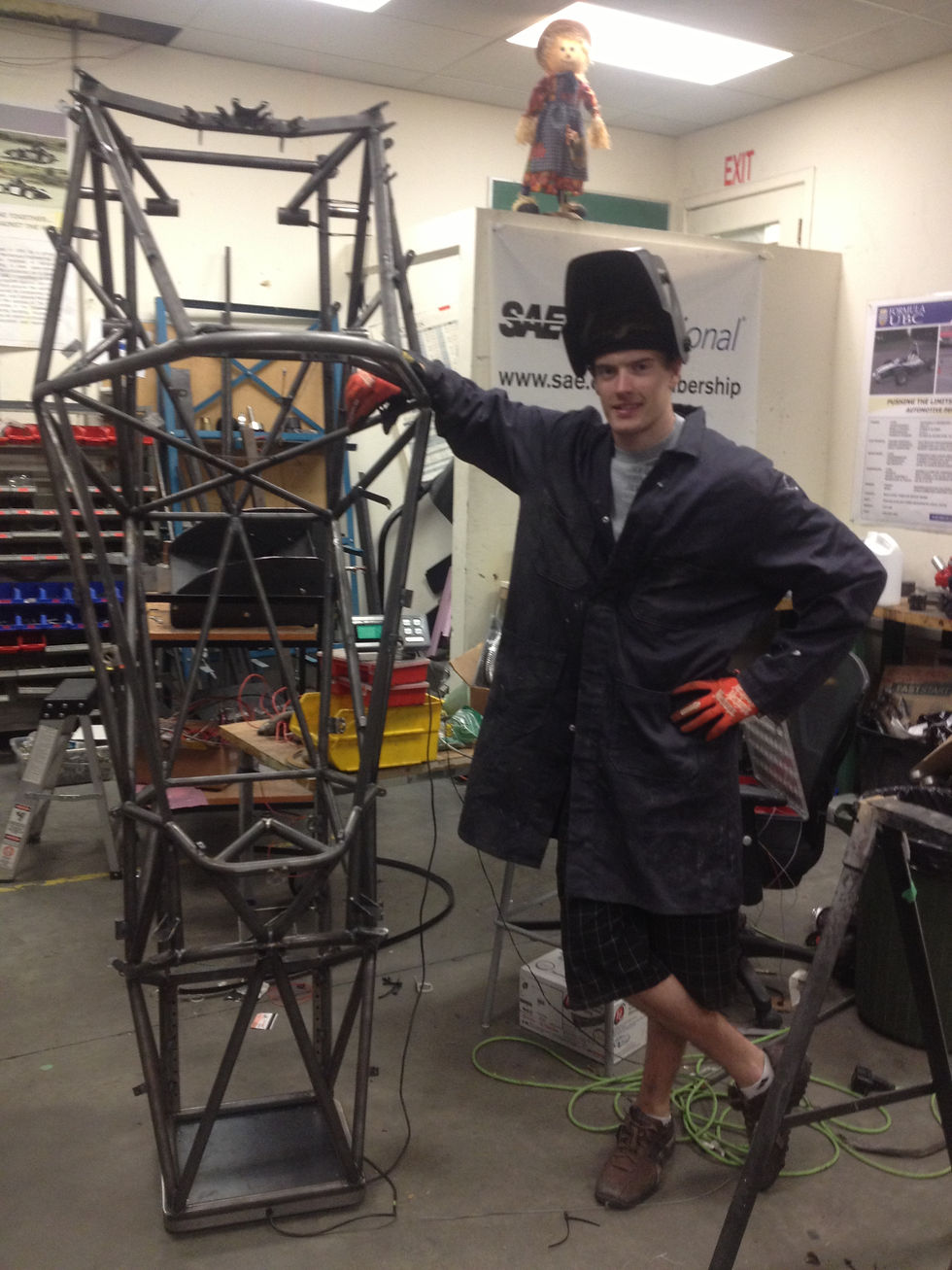
For the 2011-2013 season I held the position of Lead Chassis Engineer for the University of British Columbia's FSAE team. I was tasked with designing and manufacturing the steel chassis for the vehicle. The frame had strict dimensional & strength requirements set by FSAE rules, as well as torsional stiffness / node point deflection requirements set by the team. Chassis designs for the 2011, 2012, and 2013 vehicles were completed in SolidWorks using weldment tools, and torsional stiffness analysis completed with SolidWorks FEA package and ANSYS.
2013 Frame Design Review

Entire frame made of chromoly steel for optimum strength/weight. Torsional stiffness analysis done with single wheel bump method, isolating both a front wheel bump and rear wheel bump. Torsional stiffness requirements were set from estimates of how well an amateur driver could feel total lateral load transfer distribution (TLLTD) variation.

For simplicity the engine block was treated as an infinitely stiff object. It is a stressed member of the chassis, and provides strong anchor points for suspension pickup points.
Different chassis tube configurations were tested in FEA to observe their effect on torsional stiffness. Carful consideration was done when selecting tube size and thickness for support structures not defined by FSAE rules.


Construction

A rectangular steel base was used to jig the frame once design was completed. In this method, vertical sheet metal pieces surround the frame, and hold each tube in place for welding (plates were water-jet cut). To relieve joint stress from TIG welding, each node was stress relieved using propane tiger-torch (heated to ~1200F/650C and allowed to cool to room temperature).
The 2013 vehicle performed excellent at competition, completing all dynamic events, and half of the endurance event.


Comments